What is a CNC Milling?
CNC milling, or computer numerical control milling, is a machining process which employs computerized controls and rotating multi-point cutting tools to progressively remove material from the workpiece and produce a custom-designed part or product. This process is suitable for machining a wide range of materials, such as metal, plastic, glass, and wood, and producing a variety of custom-designed parts and products.
Milling utilizes a cylindrical cutting tool that can rotate in various directions. Unlike traditional drilling, a milling cutter can move along multiple axes. It also has the capability to create a wide array of shapes, slots, holes, and other necessary impressions. Plus, the workpiece of a CNC mill can be moved across the milling tool in specific directions. A drill is only able to achieve a single axis motion, which limits its overall production capability.
CNC mills are often grouped by the number of axes on which they can operate. Each axis is labeled using a specific letter. For example, the X and Y axes represent the horizontal movement of the mill’s workpiece. The Z-axis designates vertical movement. The W axis represents the diagonal movement across the vertical plane.
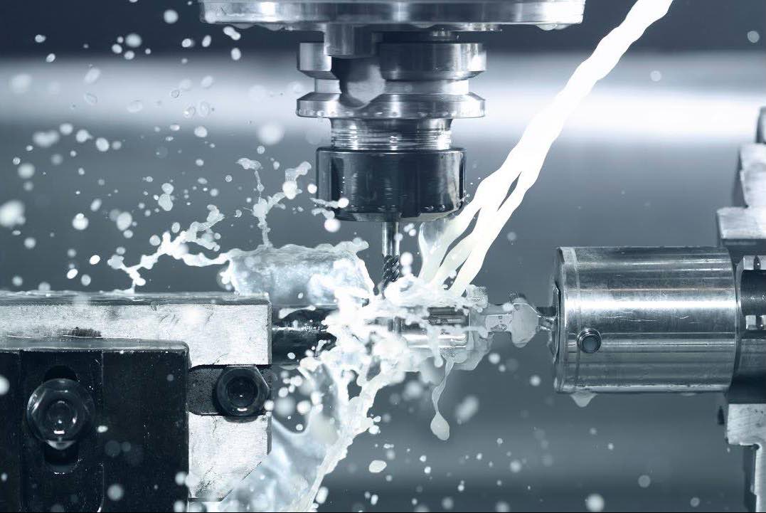
The majority of CNC milling machines offer from 3 to 5 axes. More advanced mills must be programmed with CAM technology to run properly. These advanced CNC machines can produce specific shapes that are basically impossible to produce with any manual tooling techniques. In addition, most CNC mills are equipped with a special device that pumps fluid to the cutting tool during the production process.
If you do not know what sheet metal is, you can check out our article: "Brief Description and Process of Sheet Metal Fabrication"
Process of CNC Milling
Like most conventional mechanical CNC machining processes, the CNC milling process utilizes computerized controls to operate and manipulate machine tools which cut and shape stock material. In addition, the process follows the same basic production stages which all CNC machining processes do, including:
- Designing a CAD model
- Converting the CAD model into a CNC program
- Setting up the CNC milling machine
- Executing the milling operation
The CNC milling process begins with the creation of a 2D or 3D CAD part design. Then the completed design is exported to a CNC-compatible file format and converted by CAM software into a CNC machine program which dictates the actions of the machine and the movements of the tooling across the workpiece. Before the operator runs the CNC program, they prepare the CNC milling machine by affixing the workpiece to the machine’s work surface (i.e., worktable) or work holding device (e.g., vise), and attaching the milling tools to the machine spindle. The CNC milling process employs horizontal or vertical CNC-enabled milling machines—depending on the specifications and requirements of the milling application—and rotating multi-point (i.e., multi-toothed) cutting tools, such as mills and drills. When the machine is ready, the operator launches the program via the machine interface prompting the machine to execute the milling operation.
Once the CNC milling process is initiated, the machine begins rotating the cutting tool at speeds reaching up to thousands of RPM. Depending on the type of milling machine employed and the requirements of the milling application, as the tool cuts into the workpiece, the machine will perform one of the following actions to produce the necessary cuts on the workpiece:
- Slowly feed the workpiece into the stationary, rotating tool
- Move the tool across the stationary workpiece
- Move both the tool and workpiece in relation to each other
As opposed to manual milling processes, in CNC milling, typically the machine feeds moveable workpieces with the rotation of the cutting tool rather than against it. Milling operations which abide by this convention are known as climb milling processes, while contrary operations are known as conventional milling processes.
Generally, milling is best suited as a secondary or finishing process for an already machined workpiece, providing definition to or producing the part’s features, such as holes, slots, and threads. However, the process is also used to shape a stock piece of material from start to finish. In both cases, the milling process gradually removes material to form the desired shape and form of the part. First, the tool cuts small pieces—i.e., chips—off the workpiece to form the approximate shape and form. Then, the workpiece undergoes the milling process at much higher accuracy and with greater precision to finish the part with its exact features and specifications. Typically, a completed part requires several machining passes to achieve the desired precision and tolerances. For more geometrically complex parts, multiple machine setups may be required to complete the fabrication process.
Once the milling operation is completed, and the part is produced to the custom-designed specifications, the milled part passes to the finishing and post-processing stages of production.
Metal stamping is a fast and cost-effective solution for this large-quantity manufacturing need. Click here to get understanding this metal fabrication service.
Types of CNC Milling
CNC milling is a machining process suitable for producing high accuracy, high tolerance parts in prototype, one-off, and small to medium production runs. While parts are typically produced with tolerances ranging between +/- 0.001 in. to +/- 0.005 in., some milling machines can achieve tolerances of up to and greater than +/- 0.0005 in. The versatility of the milling process allows it to be used in a wide range of industries and for a variety of part features and designs, including slots, chamfers, threads, and pockets. The most common CNC milling operations include:
- Face milling
- Plain milling
- Angular milling
- Form milling
Face Milling
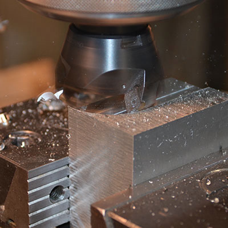
Face milling refers to milling operations in which the cutting tool’s axis of rotation is perpendicular to the surface of the workpiece. The process employs face milling cutters which have teeth both on the periphery and tool face, with the peripheral teeth primarily being used for cutting and the face teeth being used for finishing applications. Generally, face milling is used to create flat surfaces and contours on the finished piece and is capable of producing higher quality finishes than other milling processes. Both horizontal and vertical milling machines support this process.
Types of face milling include end milling and side milling, which use end milling cutters and side milling cutters, respectively.
Plain Milling
Plain milling, also known as surface or slab milling, refers to milling operations in which the cutting tool’s axis of rotation is parallel to the surface of the workpiece. The process employs plain milling cutters which have teeth on the periphery that perform the cutting operation. Depending on the specifications of the milling application, such as the depth of the cut and the size of the workpiece, both narrow and wide cutters are used. Narrow cutters allow for deeper cuts, while wider cutters are used for cutting larger surface areas. If a plain milling application requires the removal of a large amount of material from the workpiece, the operator first employs a coarse-toothed cutter, slow cutting speeds, and fast feed rates to produce the custom-designed part’s approximate geometry. Then, the operator introduces a finer toothed cutter, faster cutting speeds, and slower feed rates to produce the details of the finished part.
Angular Milling
Angular milling, also known as angle milling, refers to milling operations in which the cutting tool’s axis of rotation is at an angle relative to the surface of the workpiece. The process employs single-angle milling cutters—angled based on the particular design being machined—to produce angular features, such as chamfers, serrations, and grooves. One common application of angular milling is the production of dovetails, which employs 45°, 50°, 55°, or 60° dovetail cutters based on the design of the dovetail.
Form Milling
Form milling refers to milling operations involving irregular surfaces, contours, and outlines, such as parts with curved and flat surfaces, or completely curved surfaces. The process employs formed milling cutters or fly cutters specialized for the particular application, such as convex, concave, and corner rounding cutters. Some of the common applications of form milling include producing hemispherical and semi-circular cavities, beads, and contours, as well as intricate designs and complex parts with single machine setup.
Other Milling Machine Operations
Besides the aforementioned operations, milling machines can be used to accomplish other specialized milling and machining operations. Examples of the other types of milling machine operations available include:
- Straddle milling: Straddle milling refers to milling operations in which the machine tool machines two or more parallel workpiece surfaces with a single cut. This process employs two cutters on the same machine arbor, arranged such that the cutters are at either side of the workpiece and can mill both sides at the same time.
- Gang milling: Gang milling refers to milling operations which employ two or more cutters—typically of varying size, shape, or width—on the same machine arbor. Each cutter can perform the same cutting operation, or a different one, simultaneously, which produces more intricate designs and complex parts in shorter production times.
- Profile milling: Profile milling refers to milling operations in which the machine tool creates a cut path along a vertical or angled surface on the workpiece. This process employs profile milling equipment and cutting tools which can be either parallel or perpendicular to the workpiece’s surface.
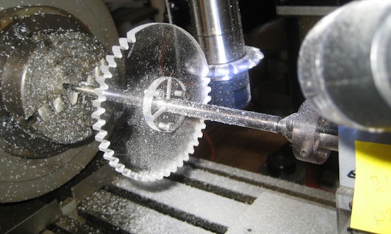
- Gear cutting: Gear cutting is a milling operation which employs involute gear cutters to produce gear teeth. These cutters, a type of formed milling cutters, are available in various shapes and pitch sizes depending on the number of teeth necessary for the particular gear design. A specialized lathe cutter bit can also be employed by this process to produce gear teeth.
- Other machining processes: Since milling machines support the use of other machine tools besides milling tools, they can be used for machining processes other than milling, such as drilling, boring, reaming, and tapping.
For more information about sheet metal fabrication industry, click here to get started to Australian General Engineering Vietnam's blog.
Resource: https://www.thomasnet.com